 |
Page 2 |
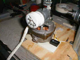
| This shows the fan motor with the fixed and adjustable caps installed. The fixed cap(behind) was epoxied to the reciprocating shaft on the fan motor. The adjustable cap can be moved side to side, tightened with the two wingnuts. The bolts were epoxied to the fixed cap. It is tough to see, but Teflon tape is super glued to the outside of the adjustable cap. What does it do? This mechanism drives the rod that guides the wire from side to side onto the spinning bobbin. |
|
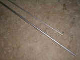
| Next I needed to complete the wire guide assembly. I went to the local hardware store and bought two aluminum rods. The solid rod is 6mm, while the tube is 10mm with a 1mm wall. The idea is to build in a wide range of adjustment to accommodate different bobbin styles and sizes. The 6mm rod fits into the 10mm tube -- ensure that you build in this capability! |
|
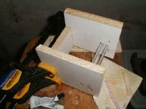
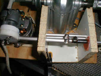
| I built the "box" for the aluminum rods out of some remnants of a cabinet I modified. This shot shows the box being clamped while the glue dries. I epoxied two rods into the box. The purpose of these rods are twofold. First, they help take the flex out of the box. Second, they serve as a guide for the reciprocating rod, keeping it from swaying side to side as it moves. The set screw assembly on the reciprocating rod will fit between the two rods. NOTE: I salvaged the set screw assembly from the sewing machine. You can also see the holes the rods will go through on the sides of the box. These holes were drilled oversize and a piece of the Teflon tape was glued in each to serve as a bearing surface for the rods. |
|
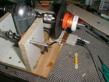
| The assembled box, shot from above. You can see the fan motor and caps on the left, the large aluminum tube contacting the adjustable cam, the stop collar (a cable clamp), and the set screw that sets the spring tension. The orange blob on the right side is the stop for the spring made from a Gatorade cap. It is hard to see, but the set screw assembly is sort of "L" shaped -- the bottom of the "L" has Teflon tape on both sides, and slides between the two aluminum rods. This keeps the wire guide from leaning toward or away from the bobbin. |
|
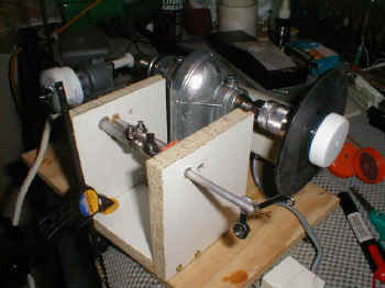
| The nearly completed winder viewed from the side.
Here you can see the wire guide (salvaged from the sewing machine) epoxied to the
solid aluminum tube. The bobbin mounts on the white cap to the right, and the wire
passes through the guide to the spinning bobbin. The wire guide moves back and forth
to guide the wire. As you can see, I deleted the large pulley from the sewing machine opting for a smaller one. The belt is a Black and Decker belt sander belt cut in half, width-wise. |
|
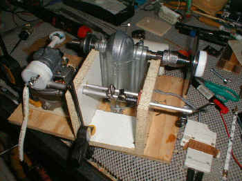
| Another view of the winder from the top. The box and fan motor have not been attached to the plywood base. I ran the winder, and successfully wound about 200 turns of thread onto an old, unserviceable pickup bobbin. Remember -- build in plenty of adjustment on the rods because not all bobbins are the same! |
|
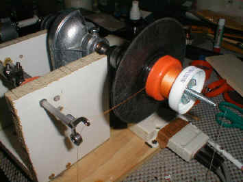
| All of the fixtures are attached to the plywood
base. I decided that I was ready to wind something. This shot shows an improvised bobbin built from a Krazy Glue container and two bottle caps. You can't see it, but the Krazy Glue container was cut to the width of a Strat bobbin, then placed between the two caps while being held with the bolt and wingnut. I tightened the wingnut, keeping the glue container centered. Once tight, I threaded the orange cap onto the threaded base. The gold thread on the "bobbin" is my first winding "material" because I haven't received my magnet wire yet. |
|
| This photo shows how I lined-up the wire guide with the bobbin. I used a .042 gauge guitar string and threaded it through the wire guide. I turned on the reciprocating mechanism, and ensured the guide made it completely from each side to the other. The string was solid enough to serve as a great guide. It took a few minutes to adjust, but in a short time the wire guide was lined up perfectly with the sides of the bobbin. Remember (again) -- build in plenty of adjustment on the rods because not all bobbins are the same! |
|
| Here is the bobbin and thread path. Note that the
bobbin is pretty flat and doesn't have any bulges or slopes after a good amount of thread
was wound. The winder did what it was supposed to on this one! Tip: Watch the speed of that motor! Ensure that you put a stop on the sewing machine speed control to keep the bobbin spinning at a constant rate, or the coil will be unbalanced! Tip: Practice with thread before you wind. Magnet wire is very fragile because 42 AWG wire is about as thick as a strand of hair! Thread is really strong, and it helps getting your machine adjusted, as well as building confidence and technique. |
|
| Back to Page 1! | |
| ATTACK HOME PICKUP PAGE | ||||||||||||||||||||||||||||||||||||||||||||||||||||
|
||||||||||||||||||||||||||||||||||||||||||||||||||||